












XCPC SI-50×100-S Pneumatic Cylinder — Standard, ISO 15552, ⌀50 mm, 100 mm Stroke, Male Rod Thread
The XCPC SI-50×100-S is a standard double-acting pneumatic cylinder to ISO 15552. Piston diameter 50 mm, stroke 100 mm, male rod thread M16×1.5, ports G 1/4″. Theoretical extend force at 6 bar is 1,178 N (≈ 120 kgf), retract force ≈ 990 N (≈ 101 kgf). Mounting and connection dimensions are fixed by ISO 15552, so the cylinder replaces Festo DSBC, SMC C96 and Camozzi Series 60 without modifying your mounting hardware.
1. Purpose and Operating Principle
The XCPC SI-50×100-S converts compressed-air energy into linear force and motion. It is a double-acting cylinder: air is supplied alternately to the piston-side port (rod extends) and the rod-side port (rod retracts). Both directions are powered, so force and speed can be controlled both ways.
A 100 mm stroke is a compact size for short operations: clamping, holding, workpiece feeding, pushers, stops and flap switching. Adjustable pneumatic cushioning at both end positions absorbs the piston’s impact on the end cap at speed.
2. Technical Specifications
| Parameter | Value |
|---|---|
| Series | SI (ISO 15552) |
| Piston diameter | 50 mm |
| Stroke | 100 mm |
| Rod diameter | 20 mm (per ISO 15552 for ⌀50) |
| Action | Double-acting |
| Rod thread | M16×1.5, male |
| Port thread | G 1/4″ (BSPP), female |
| Cushioning | Adjustable pneumatic, both end positions |
| Cushioning length | 24 mm (for ⌀32–100, per series data) |
| Medium | Compressed air |
| Operating pressure | 1–9 bar (0.1–0.9 MPa) |
| Proof pressure | 1.35 MPa |
| Operating temperature | −5 … +70 °C |
| Speed range | 50–800 mm/s |
| Extend force at 6 bar | ≈ 1,178 N (≈ 120 kgf) |
| Retract force at 6 bar | ≈ 990 N (≈ 101 kgf) |
| Manufacturer | XCPC (Ningbo Xinchao Automatization Component Co., Ltd.), China |
Forces are theoretical, F = P × piston area (for retraction, minus the rod area), with friction not taken into account. In real conditions allow a safety factor of 1.5–2.
3. Design Features
SI-50×100-S part number decoder
| Position | Meaning |
|---|---|
| SI | Series: standard ISO 15552 cylinder |
| 50 | Piston diameter 50 mm |
| ×100 | Stroke 100 mm |
| S | Rod end: male thread M16×1.5 (magnet — suffix “-B”, see ⚠️ above) |
Design solutions:
- Extruded aluminium profile barrel with tie rods per ISO 15552, aluminium end caps.
- Chrome-plated steel piston rod, rod guide bushing.
- Adjustable needle screws for cushioning on both end caps.
- Standard mounting dimensions: foot (LB), flange (FA/FB), clevis (CA/CB) and trunnion mountings fit.
4. Installation Recommendations
- G 1/4″ ports are BSPP (parallel) thread. Sealing is by the flat gasket or washer under the fitting. Do not use PTFE tape: tape fragments get into the cylinder and the valve.
- Rod thread M16×1.5 is a metric parallel thread. Attach the rod clevis, eye or coupler with a lock nut; no tape or sealants are needed.
- Alignment. The load must act strictly along the rod axis. Side load on a short stroke wears the guide bushing and rod seal fastest. If alignment is imperfect, use a self-aligning coupler or a spherical rod eye.
- Cushioning. Before start-up, close the screws, run the cylinder at working pressure and open them ¼ turn at a time until it stops without impact. With a 100 mm stroke at speeds above 300 mm/s this adjustment is especially important.
- Air preparation. Filtering and drying the air upstream extends seal life. Moisture and abrasives are the main cause of failure.
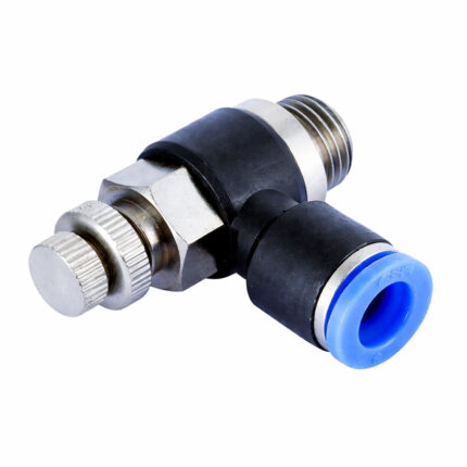
- Speed control — use flow control valves on the exhaust (meter-out), not on the supply.
5. Equivalents and Comparison
Cross-references (ISO 15552, ⌀50, 100 mm stroke):
| Brand | Part number | Series | Note |
|---|---|---|---|
| Festo | DSBC-50-100-PPVA-N3 (1366952) | DSBC | Adjustable cushioning, M16×1.5, G 1/4 |
| SMC | C96SDB50-100 | C96 | Version without magnet; with magnet — different index |
| Camozzi | 60M2L050A0100 | 60 | Magnetic version, M16×1.5, G 1/4, adjustable cushioning |
Exact Parker, Metal Work, EMC, Pneumax and Aventics numbers for this size have not been verified, so we do not list them. ISO 15552 guarantees compatibility of mounting dimensions, but before replacing, check: presence of a magnet, mounting type and rod thread.
Comparison with neighbouring SI series models on the site:
| Model | Bore | Stroke | When to choose |
|---|---|---|---|
| SI-50×100-S | 50 mm | 100 mm | Short stroke, 1,178 N force |
| SI-50×300-S | 50 mm | 300 mm | Same force, long stroke |
| SI-40×200-S | 40 mm | 200 mm | Lower force (⌀40), G 1/4″ ports |
| SI-63×300-S | 63 mm | 300 mm | Higher force, G 3/8″ ports |
6. Common Mistakes
- Choosing a non-magnetic cylinder for position sensors. The sensor will not trigger — specify the version before ordering.
- Not adjusting the cushioning after replacement. The piston hits the cap, and seals and cap wear out early.
- Installing with misalignment. Side load on the rod destroys the bushing within months.
- Sealing a G 1/4″ port with PTFE tape. The thread is parallel — tape is not needed and is risky.
- Running the cylinder at its pressure limit (9 bar and above) with no force margin.
- Ignoring air preparation. Condensate and dust are the seals’ main enemies.
7. Applications
- Conveyor lines: pushers, stops, diverters.
- Packaging and food equipment: pick-and-place units, slide gates, dosing units.
- Woodworking and furniture manufacturing: clamps, stops, feed mechanisms.
- Metalworking: clamping devices, dampers, auxiliary axes.
- Assembly stations and fixtures: locators, low-force presses.
8. Expert Opinion
“A 100 mm stroke on a 50 mm bore is a working size for clamps and pushers. On a short stroke, what kills the cylinder most often is not pressure but side load on the rod and a wrongly set cushion. When replacing, I always check three things: whether a magnet is needed for sensors, what type of mounting bracket is used and what thread the rod has. It takes a minute and saves a second order.”
Vitali Boluchevski, Lead Engineer, Acvatron SRL, 18 years of experience
9. FAQ
How does the XCPC SI-50×100-S differ from the Festo DSBC-50-100? Mounting dimensions, rod thread M16×1.5 and G 1/4″ ports are fixed by ISO 15552 on both, so the cylinder fits your equipment without modifications. The differences are price, materials and permissible pressure (see the specifications table). Before replacing, check for a magnet and the mounting type.
What force does a ⌀50 mm cylinder develop? At 6 bar the theoretical extend force is ≈ 1,178 N (≈ 120 kgf) and the retract force ≈ 990 N (≈ 101 kgf). Actual force is lower because of friction; use a safety factor of 1.5–2 when calculating the load.
Does the SI-50×100-S have a magnetic piston for position sensors? The base version in our range has no magnet. If you need position sensors, state this when ordering and we will select the magnetic version.
Is PTFE tape needed on the G 1/4″ ports? No. G is BSPP parallel thread; sealing is by the fitting’s gasket or washer. Tape can get inside the cylinder.
How do I adjust the cushioning? Close the screws on both end caps, run the cylinder at working pressure and speed, then open each screw ¼ turn at a time until the piston stops smoothly without impact.









Reviews
Clear filtersThere are no reviews yet.