










Differences: 1 Port vs 4 Ports — Which Version to Choose
Both versions perform the same job — pressure control. The difference lies in how the compressor’s pipework is arranged:
| Parameter | F × 1 (this model) | F × 4 |
|---|---|---|
| Number of G 1/4″ ports | 1 | 4 |
| Built-in manifold | No | Yes |
| Pressure gauge connection | Via external manifold or receiver | Direct to switch |
| Safety valve connection | Via external manifold or receiver | Direct to switch |
| Application | Compressors with a ready-fitted manifold | Compressors without a manifold |
| Installation | More compact, smaller size | Complete pipework at one point |
When the F × 1 version is appropriate:
- Your compressor receiver already has a multi-port manifold — the switch mounts separately, not into the manifold
- You need a compact, minimum-footprint replacement switch with no side ports
- A direct-drive compressor where the manifold, pressure gauge, and safety valve are located separately from the switch
- Non-standard pipework layouts where a single switch port is sufficient
When the F × 4 version is better:
- A standard piston compressor without a separate manifold — the F × 4 version brings everything together at one point
💡 Not sure which version you need? Send a photo of your compressor’s pipework or call: +373 22 503-580 — an engineer will identify the correct model.
How a 220V Pressure Switch Works
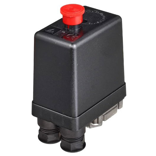
A pressure switch is an electromechanical device that automatically starts and stops the compressor motor depending on air pressure in the receiver.
Operating principle:
- Inside the housing is a diaphragm connected to the pneumatic system via the G 1/4″ thread
- When pressure drops below the lower threshold — the diaphragm releases the spring mechanism, the contact closes, and the motor starts
- When the upper threshold is reached — pressure compresses the diaphragm, the contact opens, and the motor stops
- The cycle repeats automatically without operator intervention
Two adjusters under the cover:
- Screw P (large spring) — cut-out pressure (upper threshold)
- Screw dP (small spring) — difference between upper and lower threshold (hysteresis)
Example: P = 8 bar, dP = 2 bar → compressor cuts out at 8 bar, cuts in at 6 bar.
Which Compressors Is It Compatible With
By voltage: 220V single-phase compressors only. For 3-phase 380V compressors use the Condor MDR3 series.
By thread: G 1/4″ Female (internal, parallel/cylindrical). Standard for most compressors up to 2.2 kW.
By pipework layout: compressors with a separate manifold where the pressure gauge, safety valve, and air line connect to the receiver or a separate distribution block — not through the switch body.
Compatible models:
- Remeza AirCast LB20, LB24 (single-phase versions up to 2.2 kW) with a separate manifold
- MZB piston compressors 220V with pre-fitted receiver pipework
- Chinese piston compressors 50–100 litre / 220V with an installed manifold
- Any compressor with G 1/4″ thread at the switch mounting point where a single port is sufficient
⚠️ Check before ordering: G 1/4″ (parallel/cylindrical) and R/NPT 1/4″ (tapered/conical) are different thread standards. They look similar but are not interchangeable. Most European and Chinese compressors use G 1/4″.
Technical Specifications
| Parameter | Value |
|---|---|
| Supply voltage | 220V AC, single-phase, 50 Hz |
| Connection thread | G 1/4″ F (internal, parallel/cylindrical) |
| Number of ports | 1 (F × 1) |
| Unloader valve | Not included |
| Pressure adjustment | Screw P (upper threshold) + screw dP (hysteresis) |
| Housing material | Die-cast aluminium / silumin |
| Application | Single-phase piston compressors with a separate manifold |
| Pressure adjustment range | ≈ 3–10 bar |
| Compatibility | Remeza AirCast, MZB and equivalents with G 1/4″ |
How to Set the Pressure Switch
Step 1. Disconnect the compressor from the power supply and bleed the receiver down to zero pressure.
Step 2. Remove the switch cover (2–4 screws).
Step 3. Locate the two adjustment screws:
- Large screw (P) — upper pressure threshold (cut-out)
- Small screw (dP) — hysteresis (difference between cut-in and cut-out)
Step 4. Turning screw P clockwise increases cut-out pressure. Anti-clockwise decreases it.
Step 5. Replace the cover, restore power, start the compressor, and verify switching on the pressure gauge.
Typical setting for an 8 bar compressor: P = 8 bar, dP = 2 bar → cuts in at 6 bar, cuts out at 8 bar.
Comparison of All 220V Pressure Switch Versions in the Acvatron SRL Range
| Model | Ports | Unloader valve | When to choose |
|---|---|---|---|
| 220V G 1/4″ F × 1, no valve | 1 | No | Compressor with separate manifold, external unloader |
| 220V G 1/4″ F × 4, no valve | 4 | No | Compressor with separate unloader, no manifold |
| 220V G 1/4″ F × 4, with valve | 4 | Yes (6 mm) | Standard 220V piston compressor |
Expert Opinion
“The F × 1 version is chosen less often than F × 4, but in certain layouts it’s exactly the right fit. The typical case is a compressor with a metal pipework assembly on the receiver, where the manifold, gauge, and safety valve are already welded or screwed into separate receiver ports, and the switch has a single dedicated G 1/4″ threaded hole. Fitting an F × 4 there is excessive and awkward — the three spare ports would all need plugging. The F × 1 drops in cleanly with nothing wasted. The main thing to check before ordering is that you genuinely have G 1/4″ and not R (NPT) 1/4″. It’s a common mistake, especially on Asian-made equipment: NPT thread is slightly tapered and looks like G, but it seizes and leaks when tightened. One way to tell: if the thread narrows toward the end — it’s NPT; if it’s uniform all the way — it’s G.”
Vitaly Boluchevsky, Chief Engineer at Acvatron SRL, 15 years in the industry
FAQ
❓ What is the difference between the F × 1 and F × 4 switch? The number of G 1/4″ threaded ports: F × 1 has one port, F × 4 has four. With a single port, the switch can only connect to one point — typically a receiver or manifold port. All other connections (pressure gauge, safety valve, air supply line) must be made via a separate manifold.
❓ Is an unloader valve needed when using the F × 1? It depends on the compressor design. If your compressor has a built-in unloading mechanism in the cylinder head or a separate solenoid unloader valve — this version without the valve is correct. If no unloader is present — you need a switch with a built-in unloader valve (the version with the 6 mm side port).
❓ Can a pressure gauge and safety valve be connected to the F × 1 switch? No — the single G 1/4″ port is taken up by connecting the switch to the receiver or manifold. The pressure gauge and safety valve must be connected to separate receiver ports or via an external manifold.
❓ How do I tell whether my thread is G or NPT? Inspect the thread: if it is parallel (uniform diameter throughout) — it is G 1/4″. If it narrows slightly toward the end (tapered) — it is NPT 1/4″. A G nut on an NPT fitting will tighten with resistance but will leak or strip the thread. If in doubt — call us or bring the old switch in for comparison.
❓ Can this switch be used on a 380V compressor? No. This switch is rated for 220V single-phase circuits. For 3-phase 380V compressors use the Condor MDR3 series — they have a 3-pole contact and appropriate insulation rating.