











Air Preparation for Painting: A Complete Guide to Choosing Paint Filters and Purifying Compressed Air

Paint job quality doesn’t depend only on the material, the spray gun, and the painter’s skill. The compressed air fed into a spray gun comes into direct contact with the coating material as it leaves the nozzle — and if that air contains moisture, oil, or solid particles, the result will be ruined no matter how expensive the paint was. This article walks through the entire path air takes from the compressor to the spray gun: what contaminants appear, what standards air for painting must meet, which paint filters are needed and in what order to install them, and the most common mistakes seen in practice.
1. Why Air Preparation Is Critical Specifically for Painting
Many pneumatic tasks tolerate “dirty” air straight from the compressor without issue — inflating tires, blowing off parts, running impact wrenches. But painting and sandblasting require significantly cleaner, drier air, since contaminants transfer directly onto the treated surface along with the sprayed material. When compressed air contacts the coating material inside the spray gun, the presence of oil and condensed moisture can ruin the result even in the hands of an experienced painter. Air quality requirements are especially strict wherever even minor visual defects are unacceptable — automotive body painting, airbrushing, and other demanding finish work.
Typical coating defects caused by poor air preparation:
- Fish eye — small craters and pinholes in the fresh layer of paint or clearcoat, caused by microscopic droplets of compressor oil or silicone in the airflow. Oil lowers the material’s surface tension exactly at the point of contact, and the paint “pulls back” from that spot.
- Cratering and pitting — a similar effect caused by condensate droplets carried into the gun with the air; moisture prevents the material from spreading evenly across the surface.
- Clouding and loss of clearcoat gloss — the result of even a small amount of water or oil mixing with the clearcoat as it leaves the nozzle.
- Poor adhesion and later peeling of the coating — if dust particles or moisture droplets remain trapped under the paint layer.
- Slow or uneven drying — excess moisture in the spray fan disrupts film formation.
- Corrosion under a fresh coating — condensate that reaches the metal along with the air, or that gets trapped in the pores of an already-applied layer.
A separate issue is the stability of the supply pressure itself: air preparation for painting isn’t only about removing contaminants — it’s also about keeping the pressure set at the spray gun constant, since spray fan uniformity and material application quality depend directly on it. Pressure drops when several air consumers run at once cause “striping” in the coating and uneven material usage.
2. Where Compressed Air Contamination Comes From
A compressor doesn’t produce clean air — it compresses atmospheric air along with all its contaminants and adds some of its own:
- Moisture. Atmospheric air always contains water vapor. Compression sharply raises its relative humidity, and subsequent cooling (in the receiver, pipes, hoses) condenses the excess moisture into droplets. The higher the intake air temperature and the humidity in the compressor room, the more condensate forms.
- Oil. In oil-lubricated compressors (rotary screw and reciprocating), droplets and vapor of compressor oil inevitably enter the airflow from the compression chamber. Even oil-free compressors don’t guarantee a completely oil-free system — residual lubricant can remain in pipes, fittings, and the receiver from previous use of oil-lubricated equipment.
- Solid particles. Dust from the intake air, compressor wear debris (metal and rubber particles, pipe scale), and rust from the inside of old steel pipework.
3. What Air for Painting Should Be: ISO 8573-1 Purity Class
The international standard ISO 8573-1 sets compressed air purity classes based on three parameters at once: solid particle content, humidity (dew point), and oil content, with the final class expressed as three numbers separated by dots — the first for solid particles, the second for dew point, the third for oil content.
For reference — how typical tasks correspond to purity classes:
| Purity class | Typical application |
|---|---|
| 7.5.4 | Construction, mining |
| 7.4.4 | General machine building, secondary packaging |
| 6.4.4 | Pneumatic tools, servo-pneumatics, positioning systems |
| 5.4.3 | Packaging, textile and paper production |
| 1.4.2 | Painting, powder coating, air bearings |
| 1.4.1 | Optics, laser equipment, food production |
| 1.3.1 | Semiconductor manufacturing, pharmaceuticals |
For painting and powder coating work, the recommended purity class is 1.4.2 — meaning a strict requirement for solid particles (class 1), a dew point of around +3°C (class 4), and low oil content (class 2). In practice this means:
- Solid particles — filtration down to the submicron level (0.3–1 micron for the final stage, with the first stage typically catching particles 5 microns and larger);
- Pressure dew point — no higher than +3°C, which prevents condensate from forming in hoses and the spray gun even in a cool room;
- Residual oil content — no more than 0.1 mg/m³, achievable only through coalescing filtration, not mechanical cleaning alone.
It’s worth understanding: air should be cleaned exactly as much as a given task actually requires, not “with margin” beyond what’s needed — excessively fine filtration increases system pressure loss, speeds up filter clogging, and requires more frequent cartridge replacement without a real benefit to paint quality.
4. The Complete Air Preparation Chain: From Compressor to Spray Gun
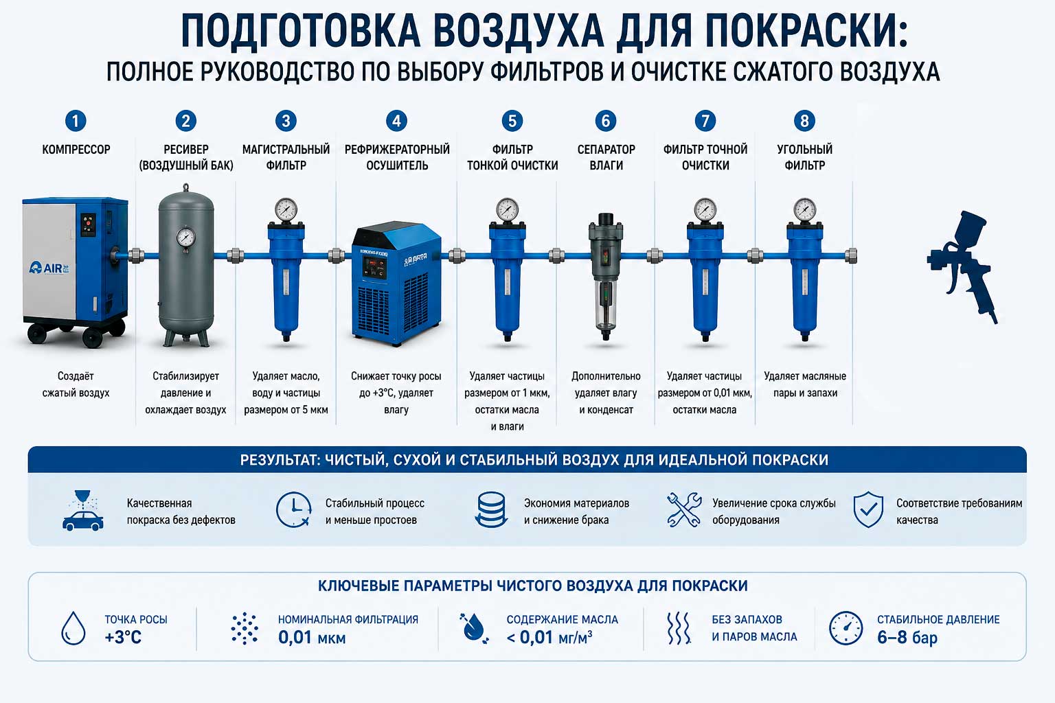
Below is the sequence of equipment that, in practice, delivers the purity class required for painting work.
4.1. Compressor and Capacity Margin
For small painting volumes, a low-power piston compressor is enough; for regular professional painting, a rotary screw compressor is the clear choice — it delivers a much steadier airflow without the sharp pressure pulsations typical of piston machines.
The key rule for sizing a compressor for a spray gun: the compressor’s rated output should exceed the spray gun manufacturer’s stated air consumption by at least 50–100%. This is because:
- actual air consumption for HVLP (High Volume Low Pressure) guns is typically 200–450 l/min at an inlet pressure of 2.0–3.5 bar;
- classic (non-HVLP) spray guns consume less air but need higher inlet pressure — typically 3.5–5 bar;
- the compressor must keep up with restoring receiver pressure between spray cycles without a pressure drop mid-job;
- extra margin is also needed for other air consumers running simultaneously in the shop (blow gun, pneumatic sander).
4.2. Air Receiver (Tank)
The receiver serves two purposes at once: it dampens compressor pressure pulsations and acts as the first stage of coarse moisture separation — thanks to the increased volume and reduced flow velocity, some of the water condensate settles to the bottom of the tank before reaching the line. Installing a receiver and an in-line separator in series can remove up to 60% of all the moisture in compressed air, which may be enough for some industrial tasks but is insufficient for properly preparing air specifically ahead of painting work — so additional equipment is required.
For a paint shop, it’s recommended to:
- drain condensate from the receiver regularly (manually or via an automatic drain);
- size the receiver’s volume with margin for the spray gun’s peak demand, not just the compressor’s average output.
4.3. Air Dryer
Even after the receiver and separator, dissolved moisture remains in the air, which will condense as temperature drops (for example, overnight in an unheated shop or inside a cold hose). A dryer forcibly lowers the air’s dew point to the required level:
- Refrigerant dryer — cools the air to +2…+5°C, condensing most of the moisture, then reheats the air back to room temperature. Delivers a dew point of roughly +3…+7°C — sufficient for most painting tasks in a heated room.
- Desiccant (silica gel) dryer — passes air through a layer of moisture-absorbing material (silica gel, activated alumina), achieving a much lower dew point (down to −40°C or lower). This level of drying is used for painting in unheated spaces, outdoor work in cold weather, or particularly demanding coating materials.
For most auto body shops and paint booths, a system of filters plus a refrigerant dryer with a dew point around +7°C is sufficient — enough to avoid moisture condensation in hoses and pipes at typical temperatures in the paint area.
4.4. The Filter Cascade: Correct Stage Order
This is the central part of the system, and it’s where mistakes are most often made. To achieve cleaner air, filters are connected in series, and the flow should move from a filter for larger particles to one for finer particles — from coarse to fine filtration, with the activated carbon filter, if needed, installed last in the chain.
The full sequence for a paint line looks like this:
- Preliminary (coarse) moisture-separating filter, 5–40 microns. Installed right after the receiver/dryer. Its job is to remove the bulk of droplet moisture, coarse dust, and pipe rust, protecting the finer, more expensive filter elements downstream from clogging quickly.
- Fine (coalescing) filter, 0.3–1 micron. Captures the finest compressor oil aerosol droplets and submicron dust through coalescence — merging small droplets into larger ones that then drain into the bowl. This stage is responsible for reducing oil content to the level required for painting.
- Activated carbon (adsorption) filter — optional, but recommended for demanding jobs. Installed last in the chain, it removes oil vapor (as opposed to droplet oil, which the coalescing filter handles), odors, and traces of volatile compounds, delivering an air purity level sufficient for the most demanding applications. For painting critical surfaces (auto bodies, products with high finish-quality requirements), an activated carbon filter significantly reduces the risk of fish eye caused by oil vapor, which the coalescing filter does not capture.
- Pressure regulator/filter immediately ahead of the spray gun (point of use). Installed as close as possible to the painter’s workstation — it compensates for pressure drop along a long hose and lets you dial in the exact pressure recommended by the spray gun manufacturer, regardless of the pressure in the shop’s main line.
Important — don’t mix up the stage order: an activated carbon filter placed ahead of the coalescing filter will quickly clog with the moisture and oil droplets that the coarser filter should be catching, and will lose its adsorption capacity many times faster. Don’t use unnecessarily fine filters where they aren’t needed — this only increases pressure loss and maintenance cost without benefit.
4.5. Line Routing
Even perfectly chosen filters won’t help if the air line is designed incorrectly:
- Pipe slope — 1–2% toward the condensate drain point, never perfectly horizontal and certainly never sloped the wrong way.
- Drop-offs to consumers should tap off the top of the pipe, not the bottom or side: condensate runs along the bottom of the main line, and a bottom takeoff will inevitably carry moisture straight to the spray gun.
- Automatic or manual drains at low points in the line and ahead of every drop to a workstation.
- Pipe material — galvanized steel, aluminum, or polymer piping resistant to internal corrosion; old black steel pipe is a source of rust and a constant burden on filters.
- Line diameter — sized with margin for cross-section, to avoid excessive pressure drop over long runs at peak flow.
5. Requirements Specific to Painting Equipment
| Parameter | Typical value for an HVLP spray gun |
|---|---|
| Inlet pressure at the gun | 2.0–3.5 bar (check the specific model’s datasheet) |
| Air consumption | 200–450 l/min |
| Recommended air purity class (ISO 8573-1) | 1.4.2 |
| Pressure dew point | no higher than +3°C |
| Residual oil content | no more than 0.1 mg/m³ |
| Final filtration grade | 0.3–1 micron (coalescing stage) |
Keep in mind that a spray gun’s rated consumption is its consumption at the moment the trigger is pulled, not an average across a shift; the compressor and receiver must be sized for peak demand, not average demand.
6. Common Mistakes When Setting Up Air Preparation for Painting
- Using only a single coarse moisture-separating filter with no coalescing stage — such a filter doesn’t catch fine oil aerosol and won’t deliver the oil purity class needed, even if the air looks dry on the surface.
- No dryer at all — relying only on the receiver and separators to remove moisture isn’t enough for a stable result year-round, especially with day-to-night temperature swings.
- Wrong filter order — an activated carbon filter ahead of the coalescing filter, or a coalescing filter with no preliminary coarse stage, leading to premature clogging.
- Skimping on the point-of-use regulator/filter — without it, pressure at the spray gun fluctuates as load on the main line changes from other air consumers.
- Ignoring scheduled maintenance — a late condensate drain and an overdue filter element replacement undo the entire air preparation system.
- Insufficient compressor capacity margin — a compressor running at the edge of its rated output can’t keep up with restoring pressure between duty cycles, starving the spray gun of air and producing an unstable spray fan.
- Installing filters right after the compressor with no receiver — drastically shortens filter element life due to peak temperatures and unconditioned airflow straight out of the compressor unit.
7. Maintaining the Air Preparation System
- Draining condensate — daily for filters with manual drains, or install automatic drains where manual servicing isn’t regular.
- Replacing filter elements — roughly every 3–6 months under normal operation; a more precise signal is visible fouling in the bowl or a pressure drop between inlet and outlet exceeding 0.5 bar.
- Checking the dryer’s dew point — periodic checks (via the built-in indicator or an external instrument), especially ahead of seasonal temperature swings.
- Inspecting the condition of main-line piping — a visual check for corrosion, especially in systems with steel pipe lacking internal anti-corrosion coating.
- Keeping a maintenance log — recording cartridge replacement and condensate drain dates helps identify which part of the system fails most often and adjust maintenance intervals accordingly.
8. Final Checklist for Air Preparation for Painting
- Compressor with at least 50–100% capacity margin over the spray gun’s consumption.
- Adequately sized receiver with regular condensate draining.
- Dryer (refrigerant for heated spaces, desiccant for cold conditions or strict requirements).
- Preliminary coarse moisture-separating filter (5–40 microns).
- Fine coalescing filter (0.3–1 micron) to separate oil aerosol.
- Activated carbon filter — for demanding painting jobs, installed last in the chain.
- Pressure regulator/filter right at the painter’s workstation.
- Correctly designed air line with slope, top takeoffs, and condensate drains.
- Regular maintenance: draining condensate, replacing cartridges, checking dew point.
Following this sequence — coarse filtration, drying, fine coalescing filtration, activated carbon adsorption where needed, final pressure stabilization at the gun — delivers air meeting ISO 8573-1 class 1.4.2, which is sufficient for professional painting without the risk of coating defects caused by contaminated compressed air.