


Centrifugal Compressor – Working Principle, Specifications and Applications
A centrifugal compressor (turbocompressor) is a dynamic machine in which gas compression is achieved by converting the kinetic energy of a rotating impeller into potential pressure energy. It is used wherever very large gas volumes need to be processed — from 500 m³/h up to hundreds of thousands of m³/h — at pressures up to 40 bar and above in multi-stage configurations. Unlike piston or screw machines, the centrifugal compressor operates continuously without pressure pulsations and contains no friction seals.
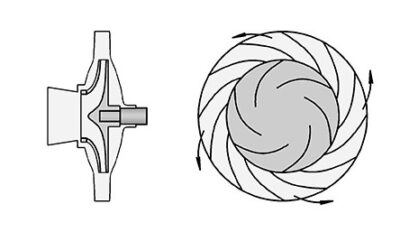
How a Centrifugal Compressor Works
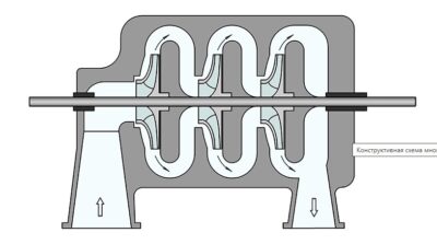
Gas enters axially at the centre of the impeller, is accelerated by the blades to high velocities (200–500 m/s) and is discharged radially into the diffuser. In the diffuser the velocity drops — kinetic energy is converted into pressure. The gas then enters the spiral volute and is directed to the next stage or to the end consumer.
Three key energy conversion zones
- Impeller (rotor) — transfers energy to the gas, accelerating it by centrifugal forces
- Diffuser — vaneless or vaned, converts velocity into pressure
- Volute (spiral casing) — collects the gas and directs it to the outlet or next stage
Technical Specifications
|
Parameter |
Value / range |
|
Operating principle |
Dynamic compression: gas acceleration by impeller + conversion of velocity into pressure |
|
Working pressure |
Up to 8–10 bar (single-stage); up to 40+ bar (multi-stage) |
|
Capacity |
500 m³/h — 500,000+ m³/h |
|
Drive power |
From 10 kW to several MW |
|
Adiabatic efficiency |
75–85% (at optimal operating point) |
|
Rotor speed |
3,000–100,000 rpm |
|
Compression ratio |
1.1–4.5 per stage; multi-stage — up to 40:1 |
|
Lubrication |
Oil (sleeve bearings) or magnetic levitation (oil-free) |
|
Air purity class |
ISO 8573-1 Class 0 (magnetic bearings) |
|
Gas cooling |
Intercoolers between stages |
|
Capacity control |
Inlet Guide Vanes (IGV), bypass, variable frequency drive |
|
Noise level |
70–90 dB(A) |
|
Standards |
ISO 10439, API 617, ISO 1217, CE, ATEX |
Types of Centrifugal Compressors
1. Single-stage centrifugal compressor
Single impeller, compression ratio 1.1–4.5. Used for ventilation, pneumatic conveying and air separation at pressures up to 3–4 bar. Compact, easy to maintain, no pulsations.
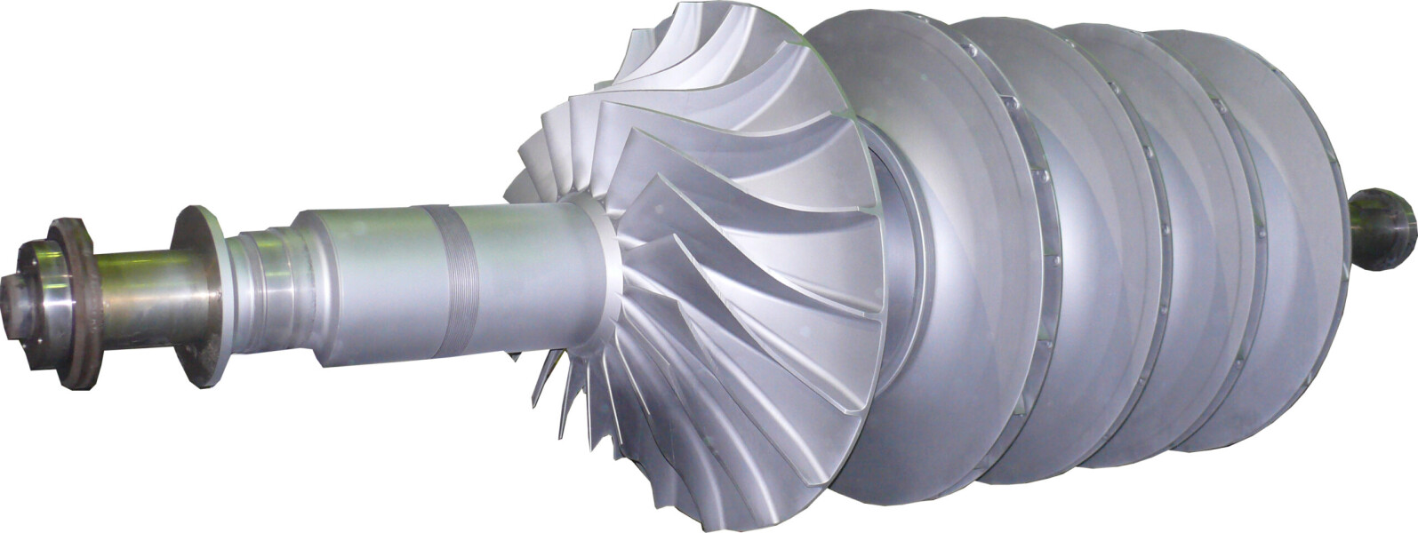
2. Multi-stage centrifugal compressor
Multiple impellers on one shaft or in separate casings with intercoolers. Compression ratio up to 40:1 and beyond. Used in petrochemicals, ammonia production and gas liquefaction. Design standard — API 617.
3. Integrally geared compressor
Multiple impellers on separate gear pinions — each impeller rotates at the optimum speed for its stage. High efficiency (up to 85%), compact layout. Typical application: industrial gas production and petrochemicals.
4. Magnetic levitation turbocompressor
The rotor is supported by active magnetic bearings — no mechanical contact whatsoever. ISO 8573-1 Class 0 air purity, no oil system. Efficiency is 8–12% higher than oil-lubricated equivalents. Service interval — 4 years and more.
Comparison with Other Compressor Types
|
Criterion |
Centrifugal |
Screw |
Piston |
|
Capacity |
Very high (>500 m³/h) |
Medium (1–50 m³/min) |
Low–medium |
|
Pressure |
Up to 40+ bar |
6–16 bar |
6–300 bar |
|
Air purity |
Class 0 (mag. lev.) |
Class 1–3 |
Class 2–3 |
|
Maintenance |
Minimal |
Every 4,000 h |
Every 250–500 h |
|
Purchase cost |
High |
Medium |
Low–medium |
|
TCO (5 years) |
Low |
Medium |
High |
Advantages of Centrifugal Compressors
1. Oil-free air without additional filtration
No friction seals and no oil in the compression path. ISO 8573-1 Class 0 is achieved by design — no activated-carbon adsorbers or costly post-filtration required. Critical for pharmaceuticals, food industry and electronics manufacturing.
2. Minimum operating costs
No consumable spare parts: no oil, filters, belts or piston rings. With magnetic levitation the service interval is 4+ years. Total Cost of Ownership (TCO) over 10 years is significantly lower than piston or screw machines of equivalent capacity.
3. Stable, pulse-free pressure
Continuous, pulsation-free flow simplifies pneumatic system design, eliminates the need for large buffer receivers and reduces stress on pipework and valves.
4. High capacity in a compact casing
A centrifugal compressor delivers 10–100 times more gas than a piston machine of similar size. This makes it irreplaceable in large-tonnage industries — metallurgy, chemicals and power generation.
5. Flexible capacity control
Inlet Guide Vanes (IGV) change the flow angle without reducing efficiency. Combined with a variable frequency drive, the control range reaches 40–100% of rated capacity without surge.
Fields of Application
- Oil & gas — natural gas transport, reservoir injection, gas processing
- Petrochemicals & chemicals — ammonia, methanol, ethylene production; process gas compression
- Metallurgy — blast furnace blowers, oxygen converters
- Industrial gas production — air separation (oxygen, nitrogen, argon)
- Pharma & food — oil-free Class 0 air for sterile processes
- Water treatment — aeration of bioreactors (blowers)
- Electronics manufacturing — ultra-clean air for cleanrooms
- Power generation — gas turbine boosters, boiler air supply systems
- Cement & mining — pneumatic powder conveying, mine ventilation
Bolucevschi Vitali, mechanical engineer, industrial compressor specialist, 16 years of experience | Acvatron
«Centrifugal compressors belong to a different category compared to screw or piston machines. Their key advantage is not pressure but scale: where clean air is needed in volumes of 500 m³/h and above at reasonable pressures, there are virtually no alternatives. In recent years, magnetic-levitation turbocompressors have taken over the wastewater treatment niche — blowers for bioreactor aeration, where roots blowers previously operated. Payback period: 2–3 years, solely from savings on electricity and oil. For small facilities with consumption below 10 m³/min, a centrifugal machine is not economically viable — a screw or rotary vane compressor would be the right choice.»
Standards and Regulatory Framework
- ISO 10439 — centrifugal compressors for petroleum, chemical and gas industry
- API 617 — axial and centrifugal compressors for petrochemical and gas services
- ISO 1217 — methods for measuring volumetric performance of compressors
- ISO 8573-1 Class 0 — compressed air purity (oil-free versions)
- ATEX — directive for potentially explosive atmospheres
- CE / PED 2014/68/EU — conformity with European Union requirements
Surge in Centrifugal Compressors — What It Is and How to Prevent It
Surge is a fault condition in which the gas flow inside the compressor periodically reverses. It occurs when the flow rate drops below the minimum allowable value for a given speed and pressure. Surge is accompanied by severe shocks, vibration and can result in impeller failure.
Surge protection methods
- Anti-surge (recycle) valve — recirculates part of the gas back to the inlet when approaching the surge boundary
- Inlet Guide Vanes (IGV) — change the inlet flow angle, widening the stable operating range
- Anti-surge controller — continuously monitors the operating point and controls the valve
- Variable frequency drive — reduces shaft speed as load decreases
How to Select a Centrifugal Compressor — Key Parameters
- Determine the required capacity (m³/min or nm³/h) with a 15–20% safety margin.
- Specify the outlet working pressure and allowable inlet pressure (accounting for site altitude).
- Choose the bearing type: oil bearings — lower upfront cost; magnetic levitation — Class 0, less maintenance.
- Assess the need for intercoolers in multi-stage configurations.
- Check media compatibility: aggressive gases require special impeller coatings or alloys.
- Request the performance map and verify the operating point is well clear of the surge boundary.
Frequently Asked Questions (FAQ)
What is the difference between a centrifugal and an axial compressor?
In a centrifugal compressor the gas moves radially — from the impeller centre to its periphery. In an axial compressor the gas flows along the axis of rotation through rows of rotor and stator blades. Axial machines handle even higher flow rates (aircraft engines, gas turbines) but offer less flexibility in control. Centrifugal compressors are simpler to design and operate for capacities up to 100,000+ m³/h.
Can a centrifugal compressor handle aggressive gases?
Yes, with the correct material selection. Impellers are manufactured from stainless steel, titanium or nickel alloys, or receive protective coatings. For chlorine, ammonia or hydrogen chloride service, individual design per API 617 is required, with full specification of the gas composition.
What maintenance does a centrifugal compressor require?
Oil-bearing units: oil change every 4,000–8,000 h, annual vibration and clearance check, major overhaul every 5–8 years. Magnetic levitation units: air filter replacement annually, control system diagnostics every 2 years, scheduled inspection every 4 years. Consumable spare parts are far fewer than for piston machines.